Restoring a Vintage Admiral TV - Page 2, The Process
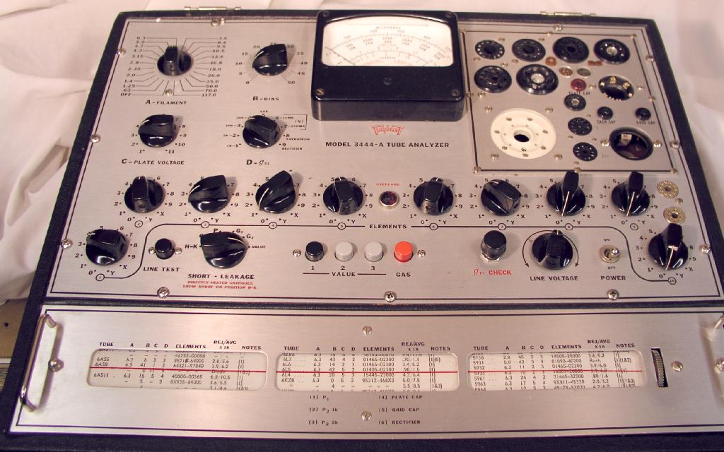
All of the tubes were tested using my Triplett 3444A Tube Analyzer.
One 12AU7 was obviously bad (lost vacuum), another 12AU7 and the 6AS5 were bad.
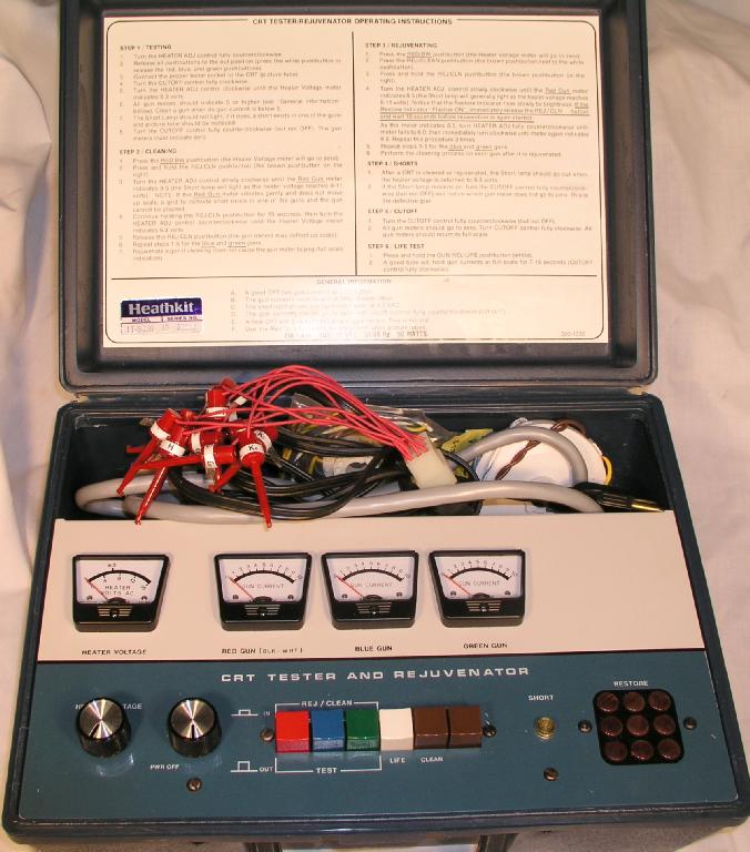
The picture tube had been checked and restored with my Heath IT-5230 CRT Rejuvenator
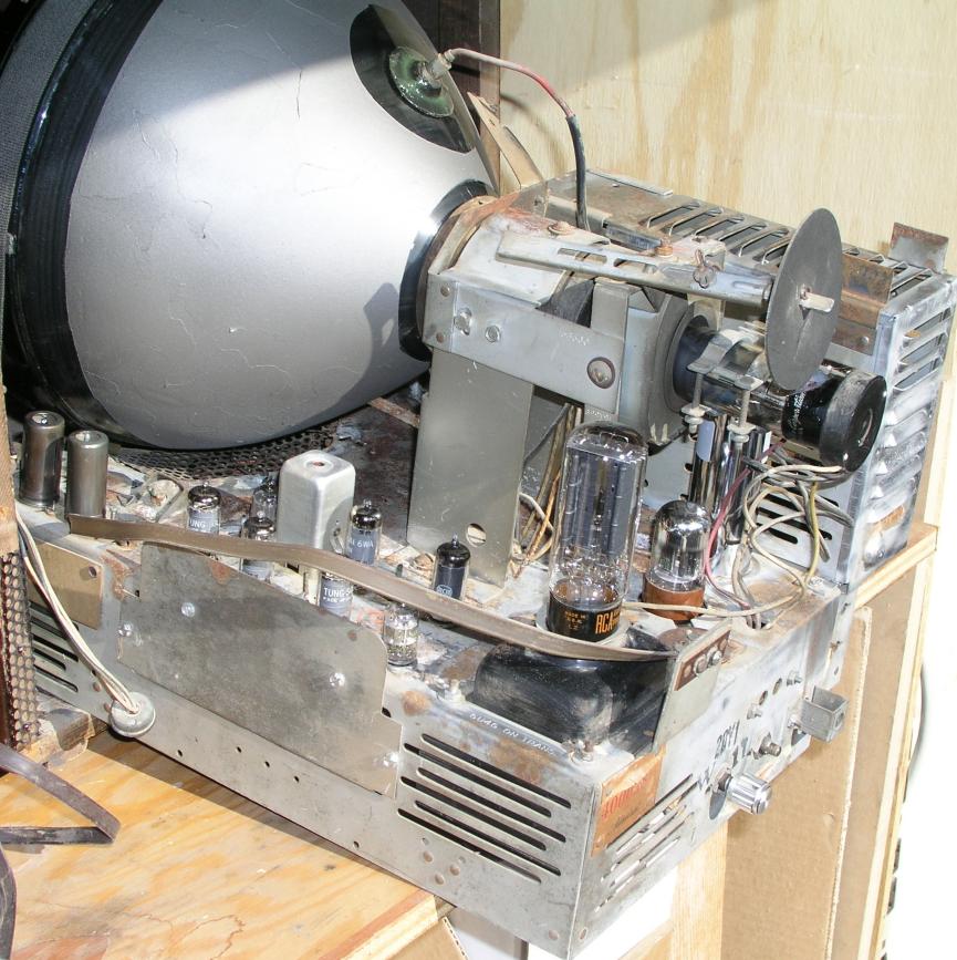
The chassis was attacked with a wire (brass) brush to remove surface corrosion,
then treated with a rust remover. Really getting rid of the rust would require more
drastic measures than I was prepared for, so I settled for a general cleanup. There was
no significant corrosion under the chassis so what was left was just cosmetic.
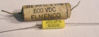
All of the tubular waxed-paper and electrolytic capacitors in the chassis were replaced
with modern equivalents. The difference between the original paper and modern polypropylene
capacitors is dramatic:
The capacitors and vacuum tubes were obtained from Antique Electronic Supply in Tempe, AZ
( They are local for me.)
The aluminum-can type multisection capacitors on the chassis are a special case.
While it is possible to disconnect the originals and leave them in place, wiring modern
tubular electrolytics in place under the chassis, I preferred to try to replace the cans
with functional and cosmetic equivalents. The source I found is DH Distributors of Wichita, KS.
They will make custom multisection capacitors to the electrical and physical dimensions of
the originals. Results are fast, very reasonable, and look beautiful. I highly recommend the service.
No online presence; phone orders to (888) 684-0050.
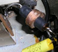
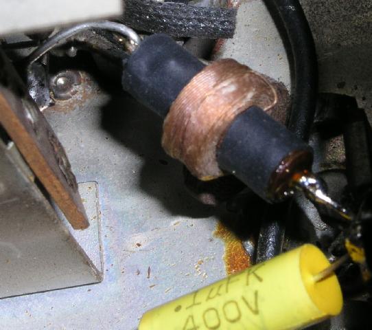
While replacing capacitors I found a damaged video peaking coil. Fortunately, the damage was confined
to the outer layer of the coil; removing a few turns located the break and the wire could be re-attached.
Replacements for these are difficult to obtain, particularly since no inductance value is shown in the schematic for it.
.
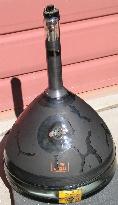
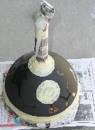
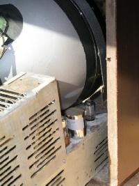
The conductive coatings on the inside and outside of a television picture tube form the plates of a
glass capacitor, which acts as a filter on the high (anode) voltage. The original coating of the 12LP4
was flaking off and cleaning the tube made it worse. I needed to find a replacement coating.
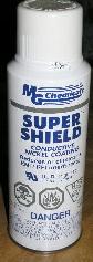
A nickel-loaded conductive paint is sold as a EMI shielding material to spray onto plastic
cases of radio equipment or computers. It works very well for this application although it's
fairly expensive at $25 a can. The material I used is "Super Shield" from MG Chemicals.
The CRT was cleaned and masked to the original extent of the coating and sprayed with a heavy coat.
.
The CRT base was repaired by gluing it to the neck with clear RTV.
The same RTV material was used to repair the high voltage lead for the CRT, where the rubber cup had begun to crack.
A heavy coating worked well to stabilize the part and avoid having to replace the entire HV cable.
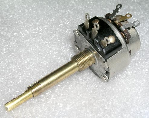
The replacement contrast / brightness control was the hardest part to find.
Dual-concentric potentiometers are nearly an extinct item in modern electronics.
The only new devices available are semi-custom parts, very expensive and the trend is
to much smaller shaft diameters.
After considerable searching, I contacted Dennis Williams at Radio Relics. He had a Philco NOS
part in stock for $10 that matched the specs I needed, although the shaft was 1" too long.
I disassembled the control and cut / filed the shafts to match the original part, then installed it.

.
Finally, the chassis was ready for checkout.
I installed only the 5U4 rectifier tube and powered it up, checking the B+ voltages.
Then, the CRT and the rest of the tubes went in, power back on , and I was greeted in a few
seconds with a bright, full raster. After some initial adjustments I had a picture and sound:
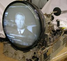
.
The set had a sharp and reasonably bright picture at this point although the CRT is clearly a bit weak.
It did exhibit retrace lines with many programs. This is a known problem with early sets, especially this
Admiral chassis. The design relies entirely on the "beyond black" video of the vertical sync pulse to
provide retrace blanking. The VITS data present in the vertical blanking interval of a modern NTSC signal
drives the picture tube back on and produces the retrace lines. I installed a modification which was apparently
recommended by the factory wherein a part of the vertical pulse is injected to the grid of the CRT.
Here is the link to the details of the mod, as posted to the rec.antiques.radio+phono newsgroup.
The modified circuit works very well indeed, with no retrace lines.
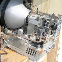
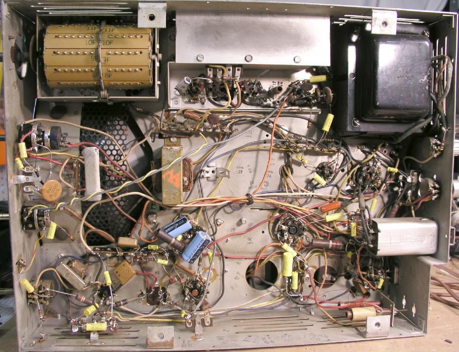
Here is the underside of the chassis with all repairs completed:

.
And the chassis from the top, reassembled:
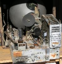
.
Page 3 - Cabinet

